In Development 3D AIBO World
Summary
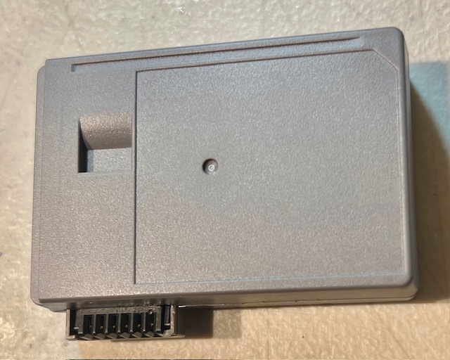
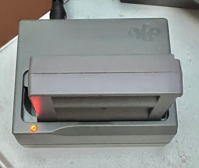
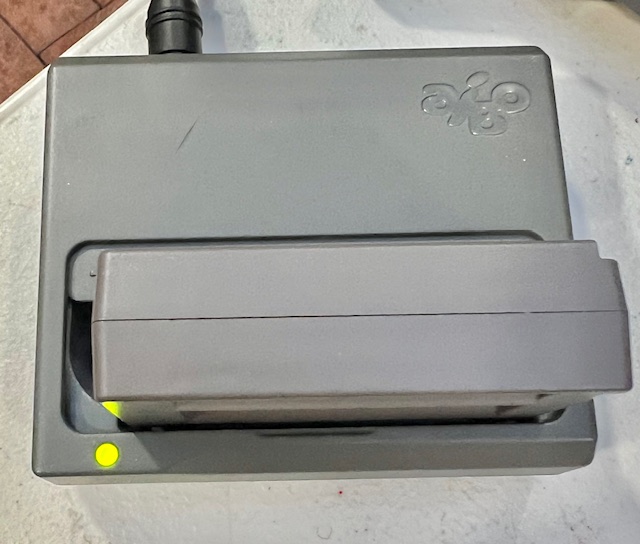
Hello from MrRobotoW I have been developing AIBO battery-pack replacements for many years across several design generations. The latest approach is the simplest and most practical I've done: • It reuses the existing AIBO battery case, connector, and thermistor • It incorporates a firmware-controlled Battery Management System (BMS) that can be updated • It remains fully compatible with the original AIBO charging systems • It also supports building completely new packs using 3D-printed cases This design minimizes complexity, avoids proprietary components, and ensures long-term maintainability for AIBO owners and developers. Select any image to zoom in or print.
New!
DIY PCB available, works with both types of cases. USB-C for pack data and updates. Use "Contact Us" if interested.
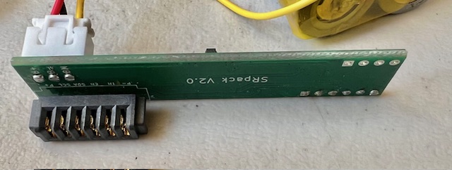
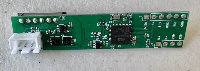
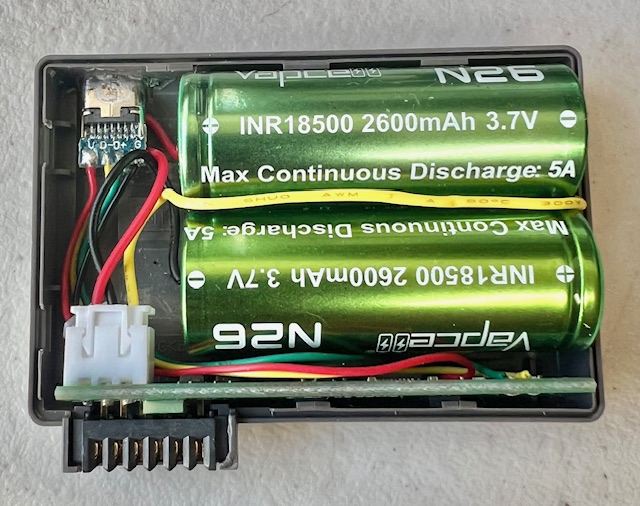
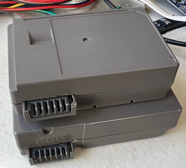
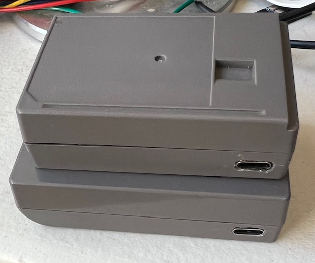
Table of Contents
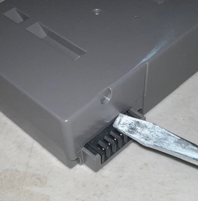
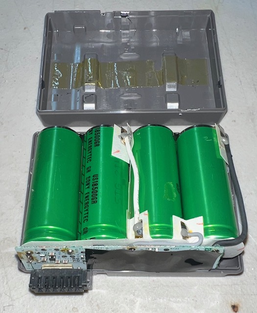
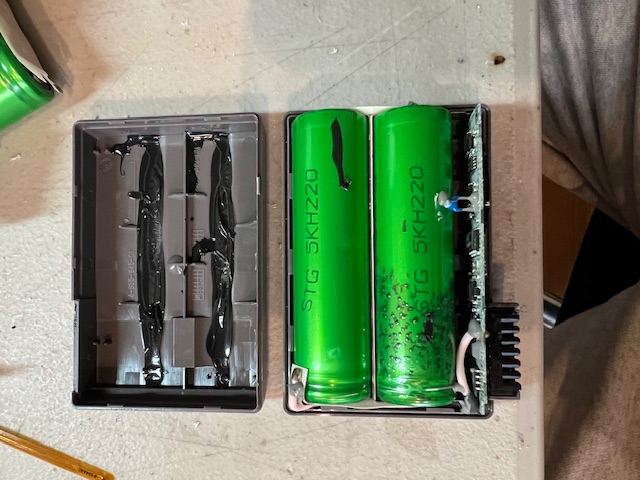
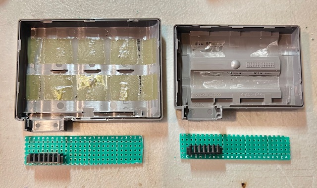
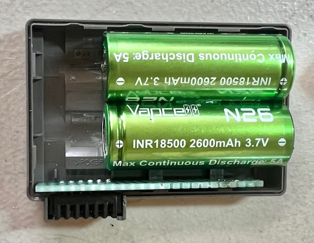
- Figure 1 – Insert a thin-blade screwdriver to lift the top half of the case. The batteries are secured with double-sided tape on the ERA-201B1, and with silicone on the ERA-301B1 and ERA-7B2, so expect to apply some upward force to lift the top off.
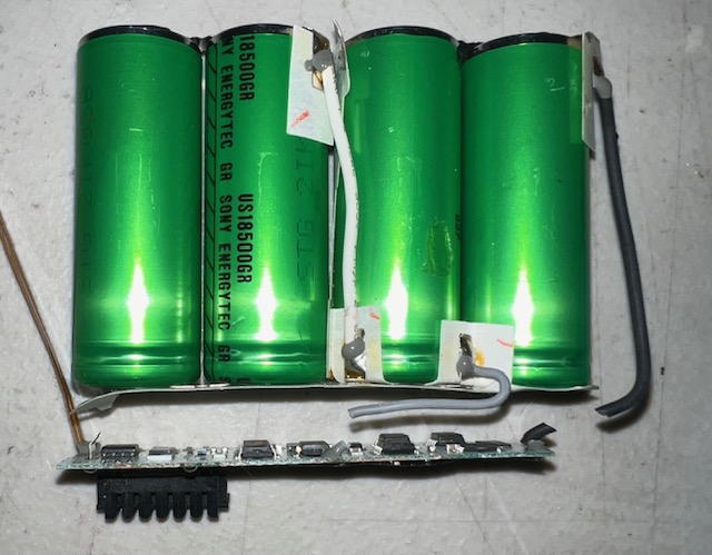
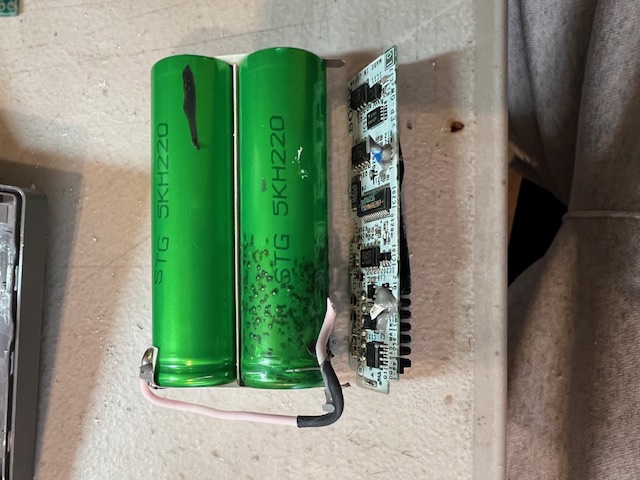
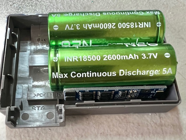
- Figure 2 – Carefully remove the batteries from the PCB cutting the connections.
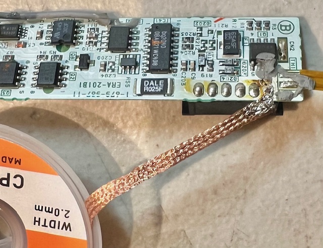
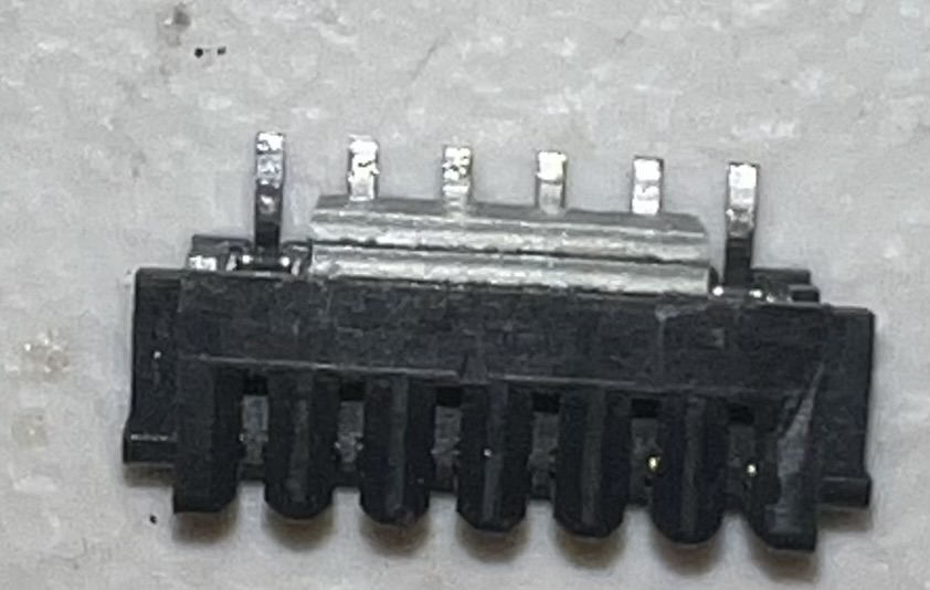
- Figure 3 – Remove connector with desoldering wick.
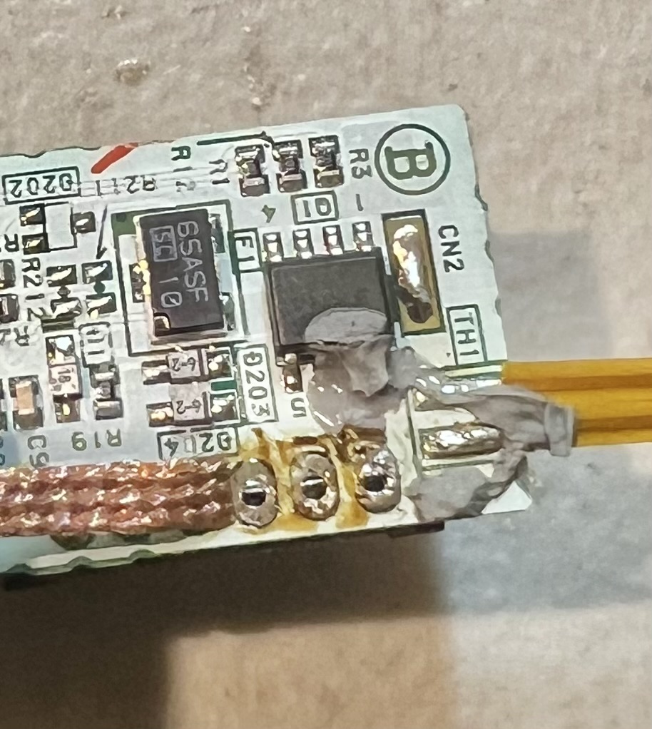
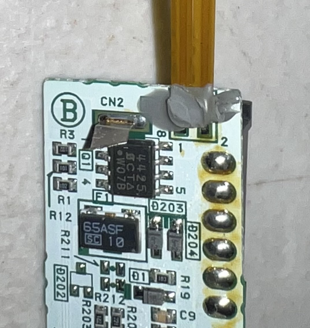
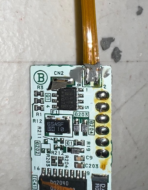
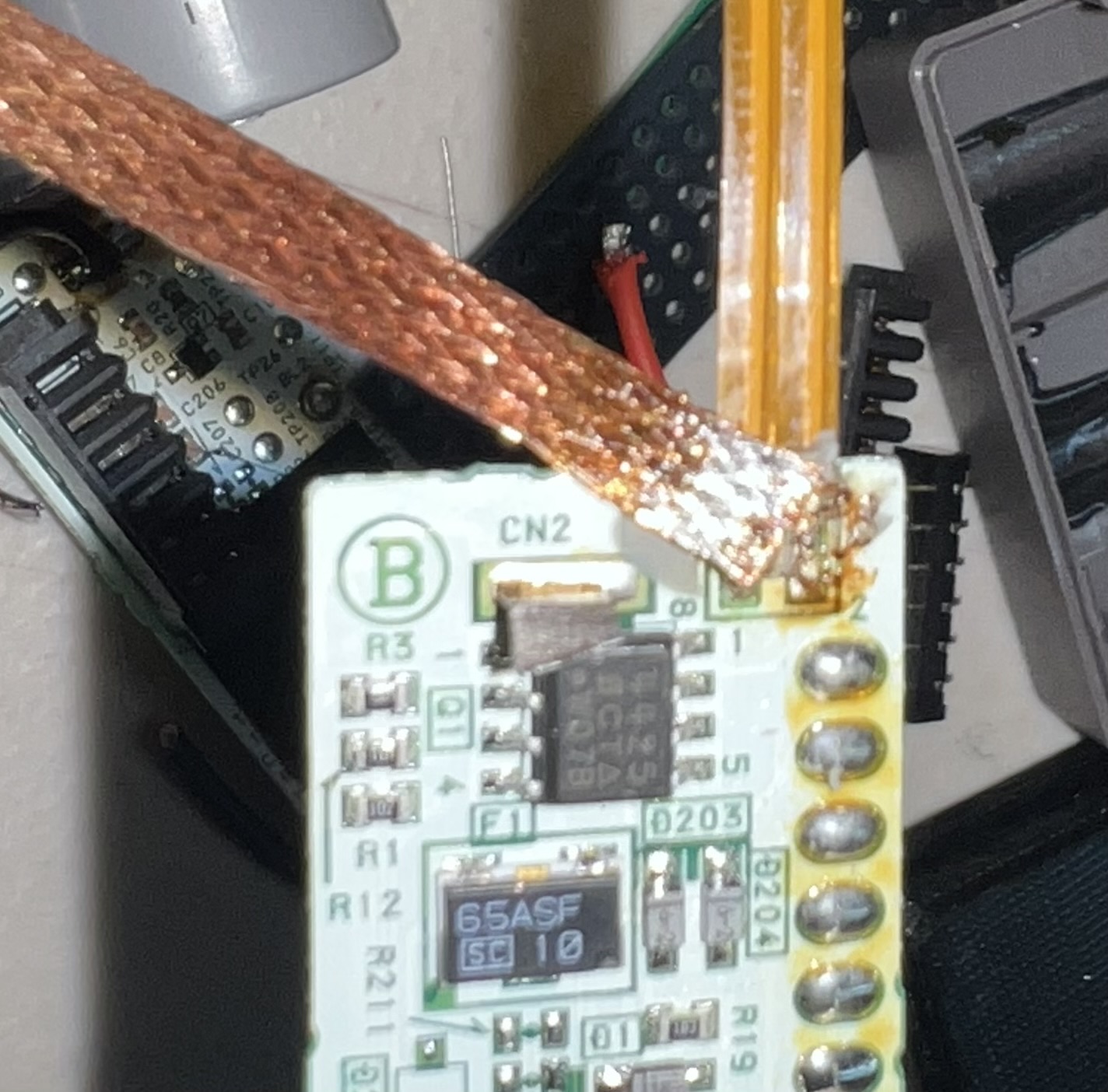
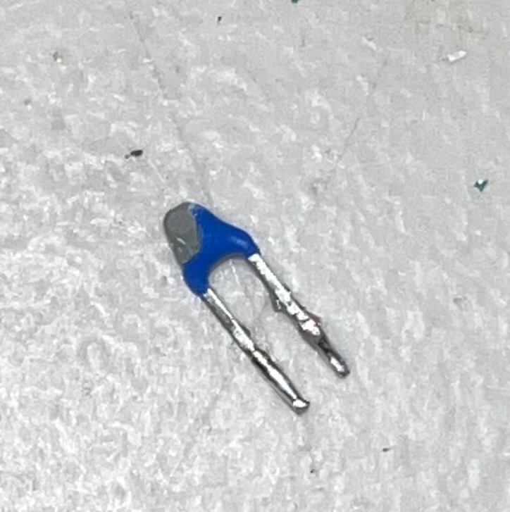
- Figure 4 – Remove the silicon from contact area on the ERA-201B1 and then the thermistor with desoldering wick.
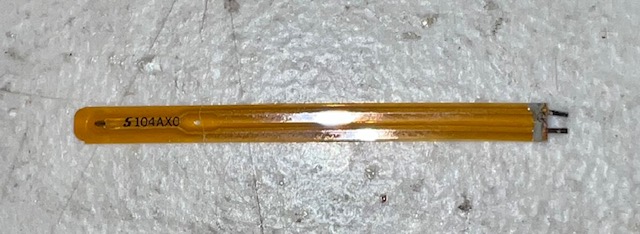
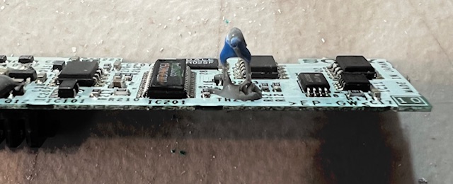
- Figure 5 – Remove the thermistor from the ERA-301B1 or ERA-7B2 using the desoldering wick.
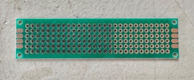
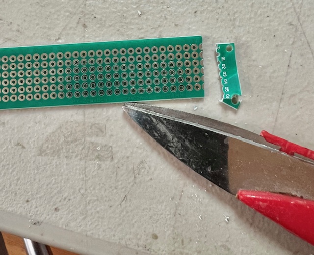
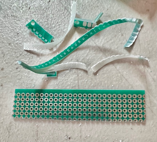
- Figure 6 – Use some good craft scissors, and Cut the perf board to similar size of the original PCB.
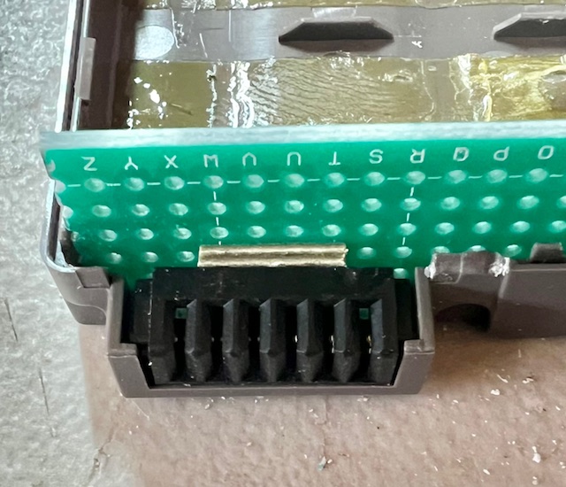
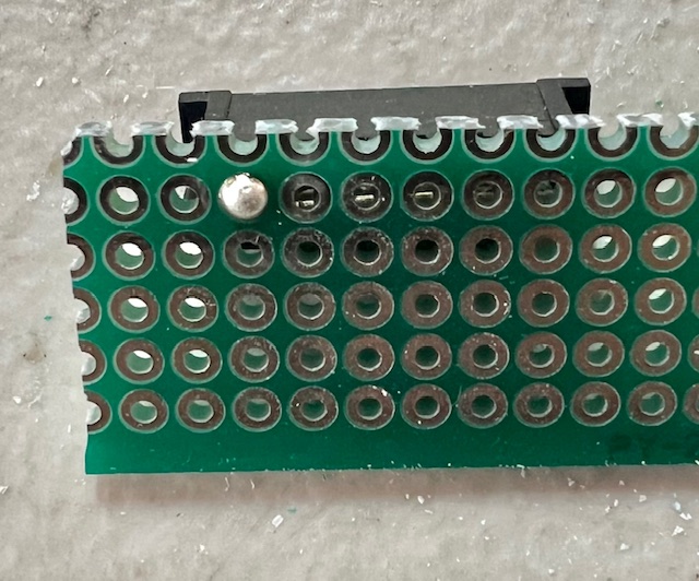
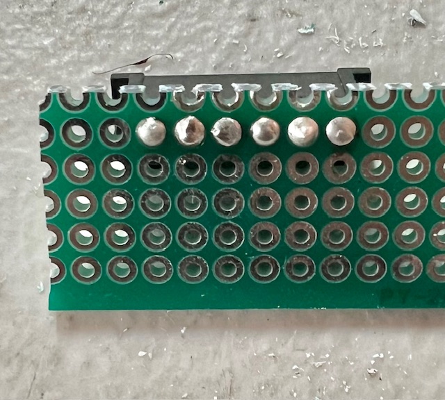
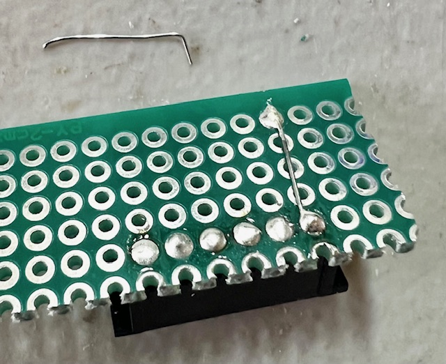
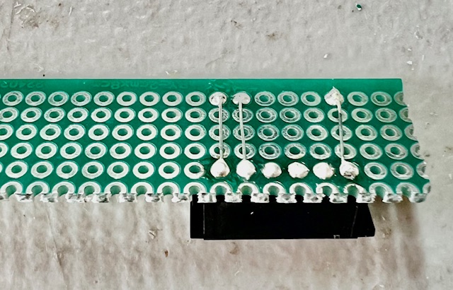
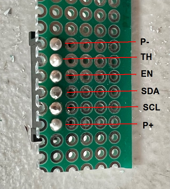
- Figure 7 – Test fit connector in the case, notice connector goes down in slot and align to the perf board pads. Only solder one pad. Double check again in the case, then solder the remaining pads. Bridge the P+, TH & P- for easier connection later.
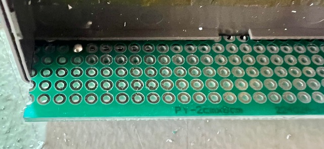
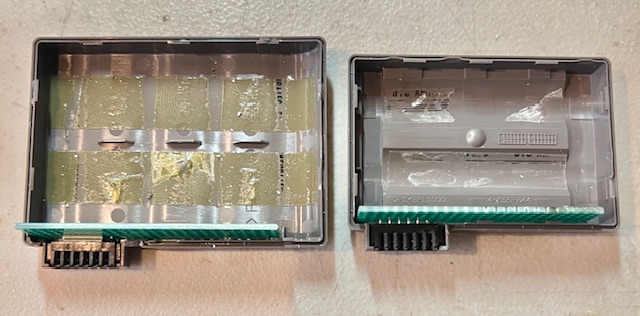
- Figure 8 – Test the perf board placement and top shell clearance close fit.
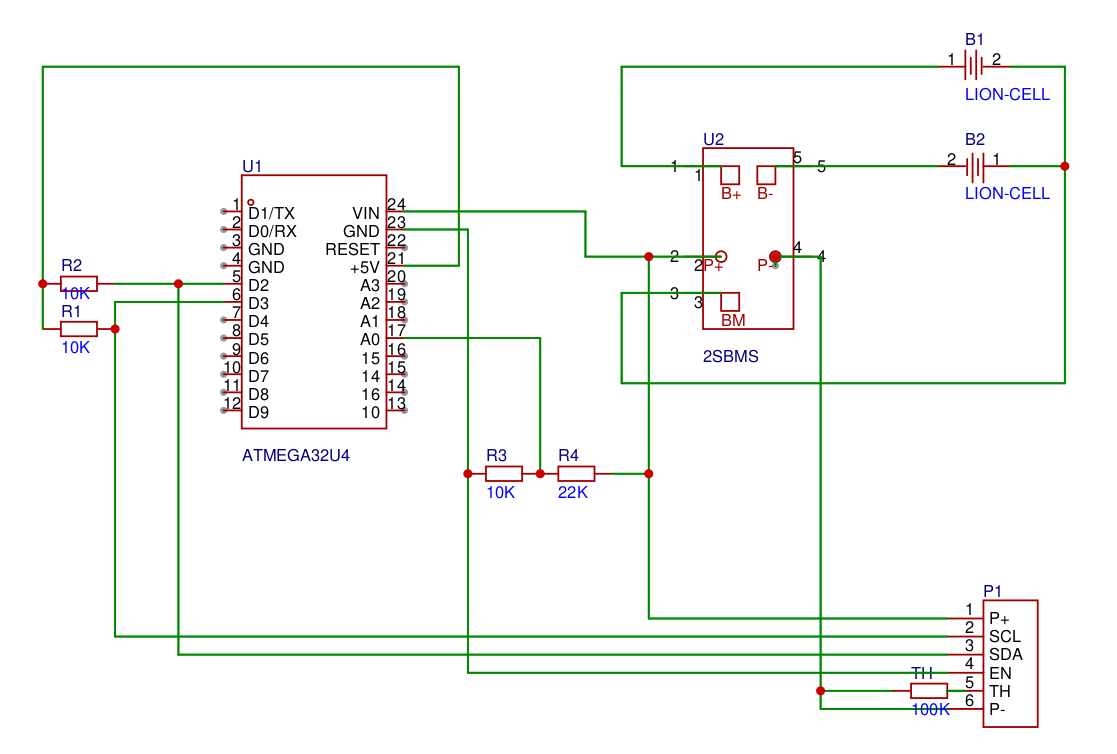
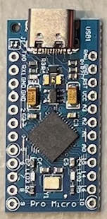
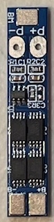
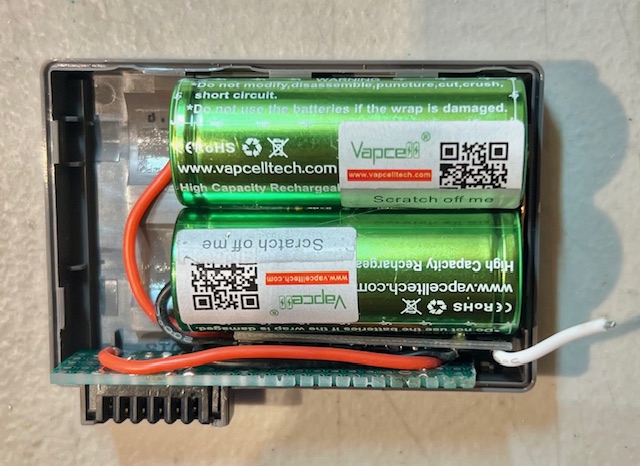
- Figure 9 – Notice the orientation of the ATMEGA32U4, 2SBMS and 6 pin connector in perfboard before beginning to wire. P+ is closest to the edge.
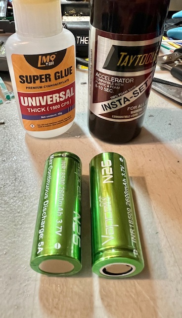
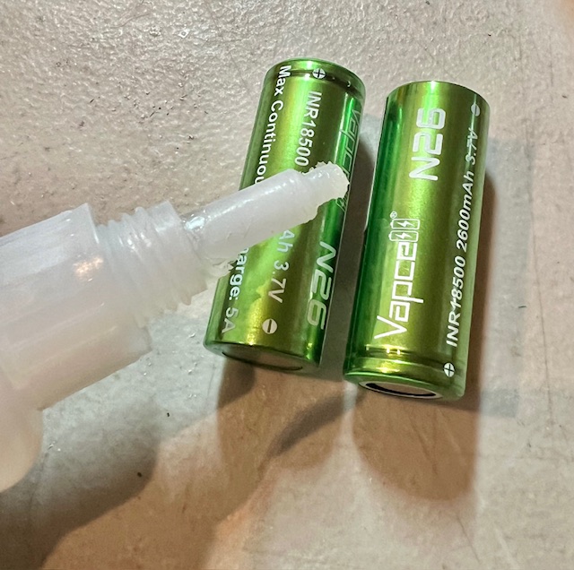
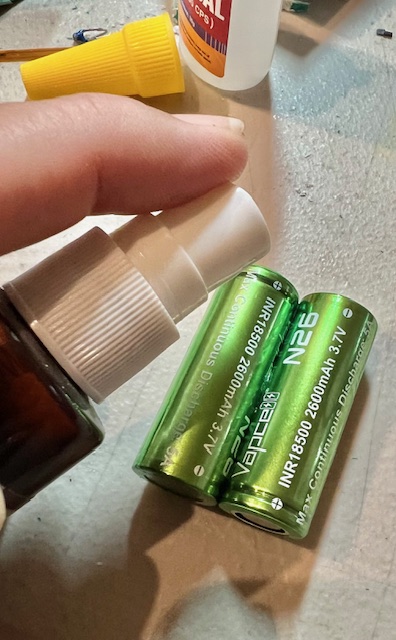
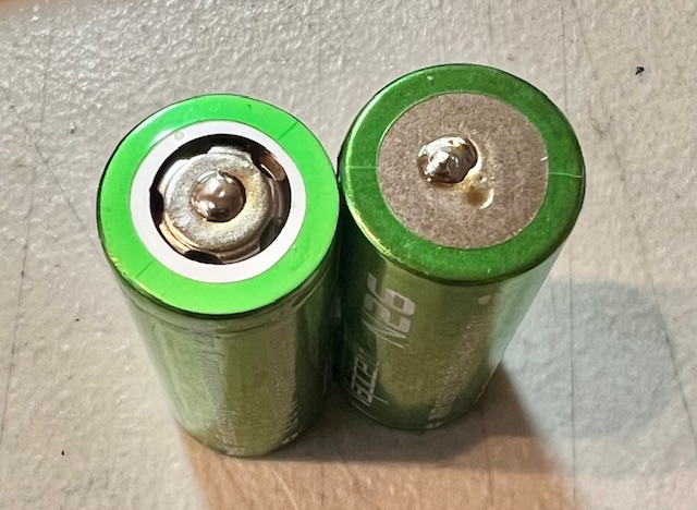
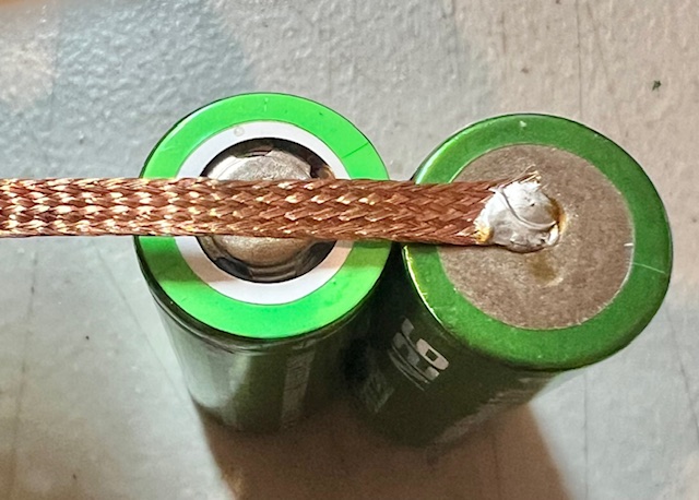
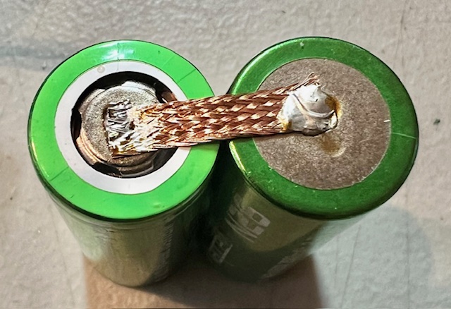
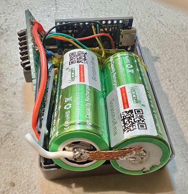
- Figure 10 – Prepare batteries by using a little instant glue and activator. Then using a piece of solder wick to make the series connection. Keeping the cells low profile for fitting in the case is important.
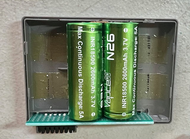
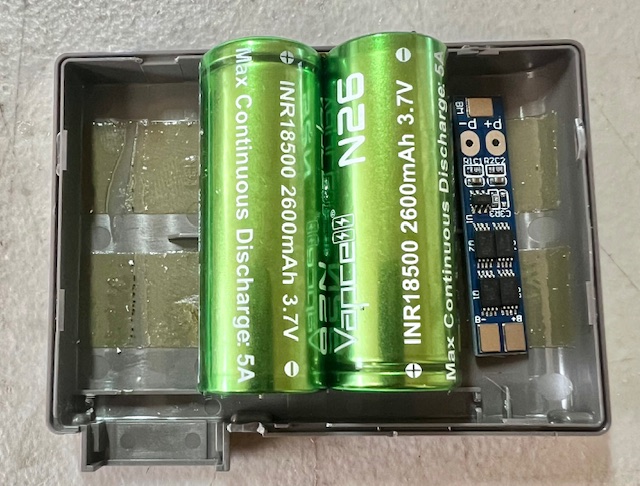
- Figure 11 – Test fit the batteries and the 2SBMS PCB location.
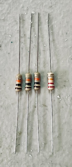
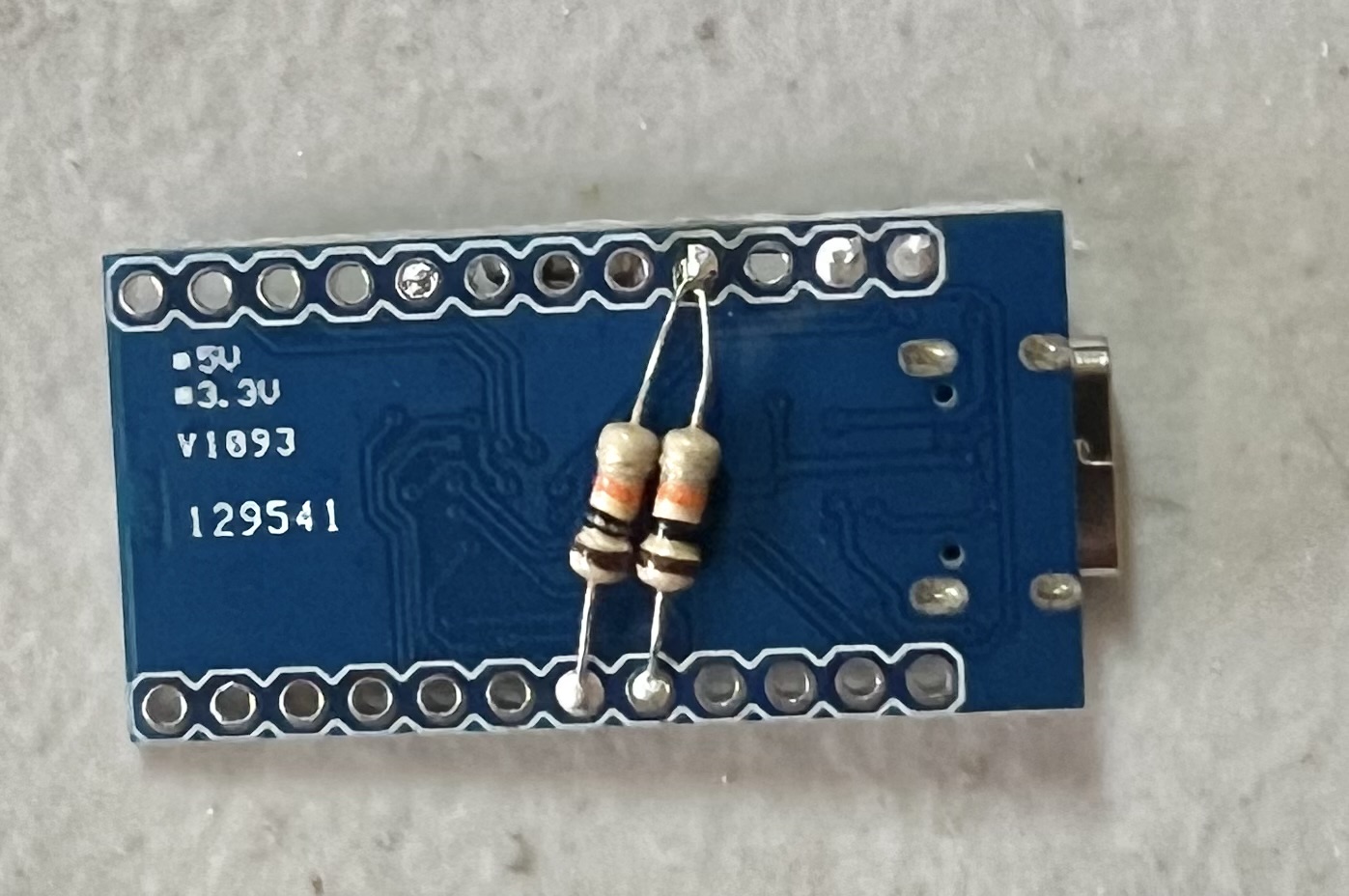
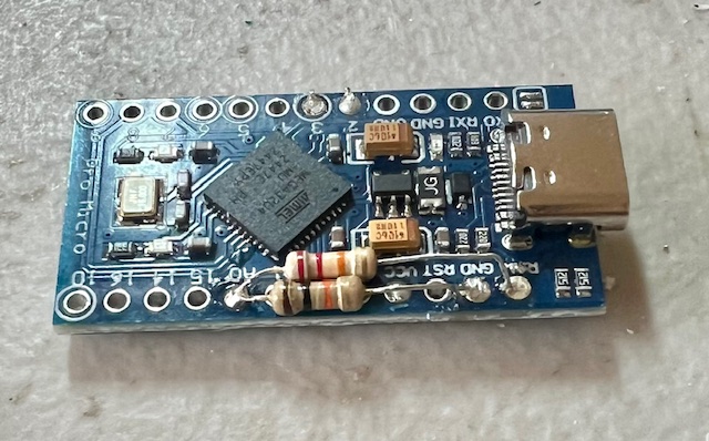
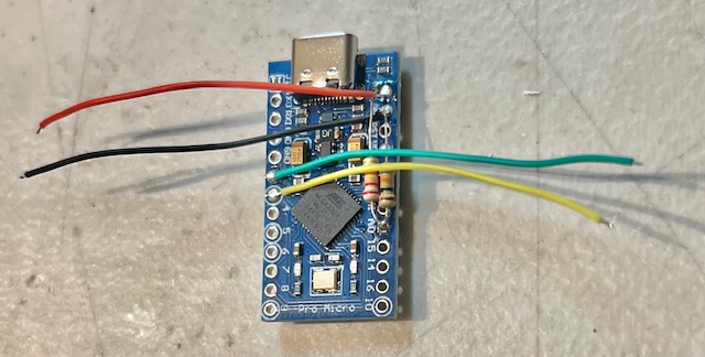
- Figure 12 – Solder the resistors on the ATMEGA32U4.
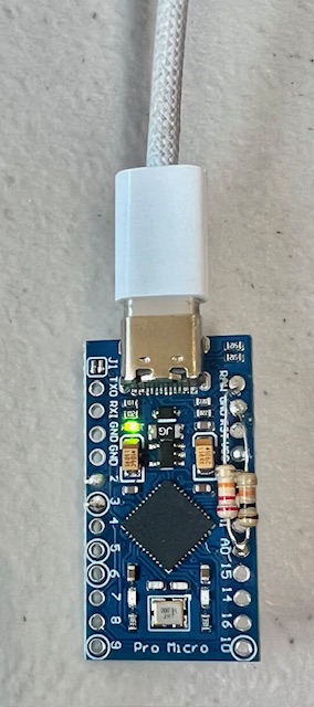
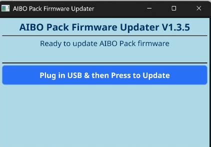
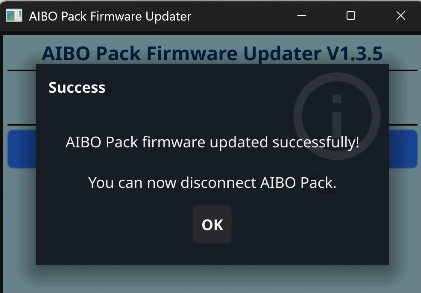
- Figure 13 – Program the ATMEGA32U4, use either the Windows or Linux updater. README.txt for details.
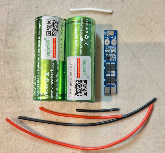
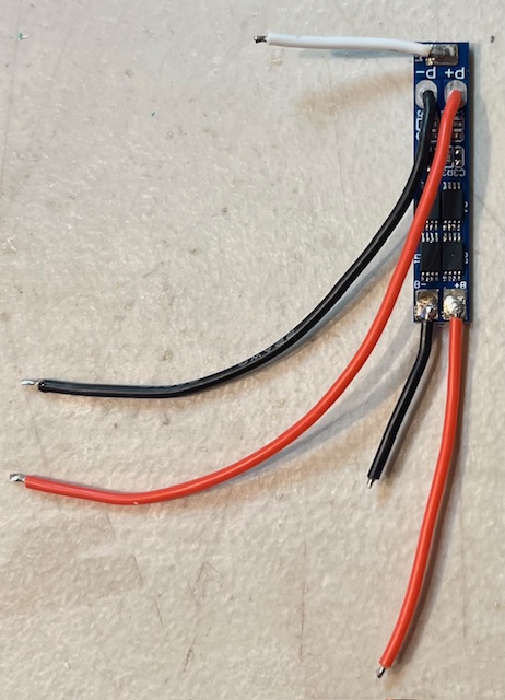
- Figure 14 – Use 22 AWG silicone wire for the power connections. For the ERA-201B1 use a 1 - Black - 90mm, 1 - Red 105mm, otherwise 1 - Black 55mm & 1 - Red 70mm from 2SBMS to perf board. Other wires are 1 - White 25mm, 1 - Red 25mm, 1 - Red 50mm
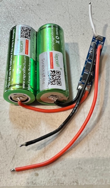
- Figure 15 – Connect only the Red and Black from the 2SBMS PCB to the batteries. The White battery middle (BM) is the last connection when the other wiring is done, otherwise the power leads are active while your still building.
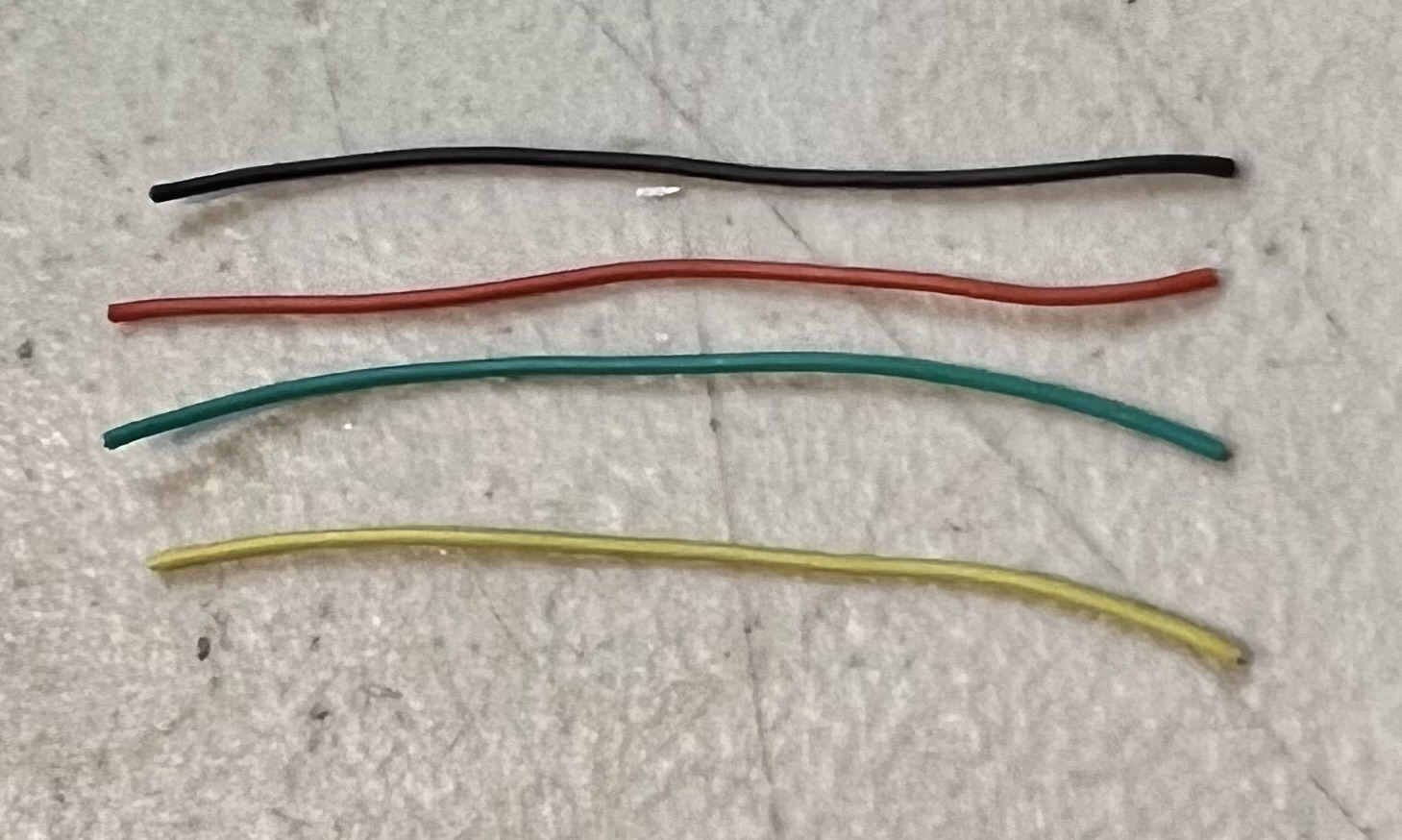
- Figure 16 – Use 30 AWG silcone wires for the ATMEGA32U4 connections to the per board. Each wire is 50mm connect each one as shown.
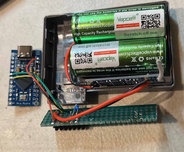
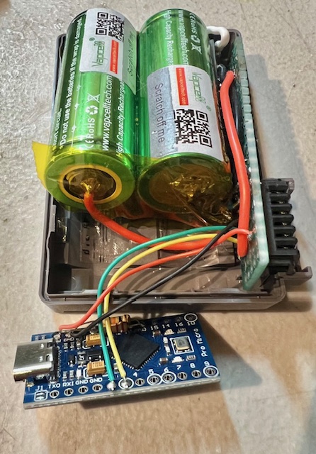
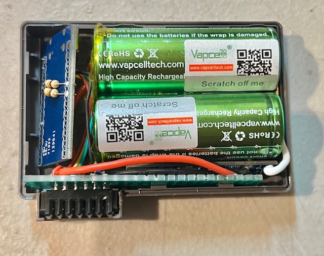
- Figure 17 – Connect the Thermistor to TH & P-, use the part matching the pack. Connect the ATMEGA32U4 wires to the perf board. Red to +P, Yellow to SCL, Green to SDA, Black to EN. Add a piece of kapton tape across the bottom of the cells. Finally connect the White BM wire, and fit everything in place.
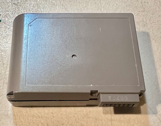
- Figure 18 – Close the case, and your ready to charge and run.
- Downloads
- Contact Us